

Self-operated (valve after) pressure Features & Specifications
The inlet pressure P1 of the process medium is transformed into the outlet pressure P2 after through throttling by the valve core and valve seat. Subsequently, P2 is transmitted through the control pipeline to the lower chamber of the actuator, exerting a force on the top plate. This force balances with the counterforce of the spring, determining the relative position of the valve core and valve seat, and ultimately controlling the pressure after the valve.When the pressure P2 after the valve increases, the force exerted by P2 on the top plate also increases accordingly. At this point, the force of the top plate exceeds the counterforce of the spring, causing the valve core to move towards the valve seat until the force of the top plate balances with the counterforce of the spring. As a result, the flow area between the valve core and the valve seat decreases, increasing the flow resistance, and ultimately reducing P2 to the set value. Conversely, when the outlet pressure P2 decreases, the direction of action is opposite to the above. This is the working principle of adjusting the pressure after the valve. When it is necessary to change the set value of the outlet pressure P2, the adjustment nut can be adjusted accordingly.
Main features
1.With pressure balancing function and high sensitivity
2.Low noise, reliable performance, and maintenance free
3.Adopting standard modular design
4.Multiple combination controls can be achieved through assembly components
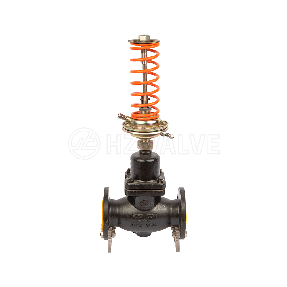
Self operated (valve after) pressure control valve (valve after pressure control) consist of control valve,an actuator, and a spring for setting pressure.Suitable for non-corrosive liquids, gases, and steam, the self-operated pressure control valve is used to control the downstream pressure in the system pipeline. When the downstream pressure rises, the control valve closes
Actuator
| Effective areas cm² | 32* | 80 | 250 | 630 |
| Pressure setting ranges (MPa) | 0.8-1.6 0.3-1.2 | 0.1-0.6 0.05-0.3 | 0.015-0.15 0.01-0.07 | 0.005-0.035 |
| The minimum pressure difference required for normal operation of the pressure valve△P | ≥0.05 | ≥0.04 | 0.01 | ≥0.005 |
| The maximum pressure difference allowed between the upper and lower chambers (MPa) | 2.0 | 1.25 | 0.4 | 0.15 |
| Materials | Diaphragm Cover: steel plate zinc coating, Diaphragm :EPDM or FKM with fiber reinforcement | |||
| Control pipelines、joint | Copper pipe or steel pipe Φ10X1(mm), Clamp connector: R1/4” | |||
Performance
| Set value deviation | ±8% | |||
| Allowable leakage( under test conditions) | Hard sealing | 4×0.01% for the rated capacity of the valve. | ||
| Soft sealing | DN15-150 10bubble/min | DN65-125 20bubble/min | DN150-250 40bubble/min | |


 HUIZHENG AUTOMATIC CONTROL VALVE GROUP CO.,LTD